
Executive summary
Understand the material before judging the value
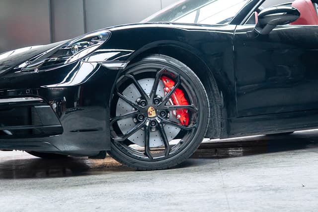
Most road carbon ceramic rotors are described as C/SiC composites, meaning carbon fibre reinforced silicon carbide. Their value is not a magical one-stop distance, but lower rotating mass, different corrosion behaviour and more consistent system response as heat accumulates.
- Daily driving: Less surface rust, usually cleaner wheels and lower rotating mass.
- Track days: Different heat capacity and stability, while pads, fluid and airflow still set the limit.
- Reality check: One-stop distance is still usually limited by tyres and ABS.
Start here
Choose the priority first, such as dust, weight, corrosion or track consistency, then confirm fitment. Fitment is where many expensive mistakes begin.
01
Performance comparison
Mass, heat behaviour, dust, corrosion and practical trade-offs.
Read section
02
Street and track life
Why road mileage is not the same as track sessions, and how to inspect the system.
Read section
03
Cost drivers
How size, hat complexity, quality control and fitment engineering affect cost.
Read section
04
Fitment and buying guide
How caliper type, rotor size and wheel clearance shape the correct choice.
Read section
What carbon ceramic brakes are
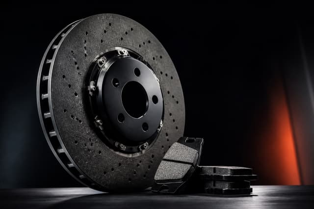
A carbon ceramic rotor is not just a disc. It combines a load-bearing structure, a working friction surface and a mounting interface. All three must survive repeated heat cycles without becoming an NVH problem.
Quick definitions
- C/SiC
- Carbon fibre reinforcement in a silicon carbide ceramic matrix.
- Bedding
- A controlled run-in process used to establish a stable transfer layer.
- Transfer layer
- A thin layer of pad material on the rotor that stabilises friction and feel.
- Runout
- Rotor movement while turning. Excess runout can cause vibration and uneven transfer.
- Fade
- Loss of braking ability when pads, fluid or hardware exceed their working range.
What you are actually buying
- Structural coreA composite rotor body that must remain stable at elevated temperature.
- Friction systemRotor surface, pad chemistry and transfer-layer behaviour.
- Mounting interfaceHat geometry, hardware stack and wheel clearance.
Use pads intended for CCB systems
A pad mismatch can directly affect transfer-layer stability, surface roughness and rotor life.
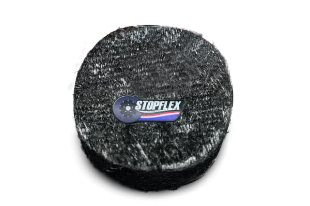
A
Rotor body: C/SiC core
Structure。A fibre-reinforced ceramic matrix intended to remain stable as temperature rises.
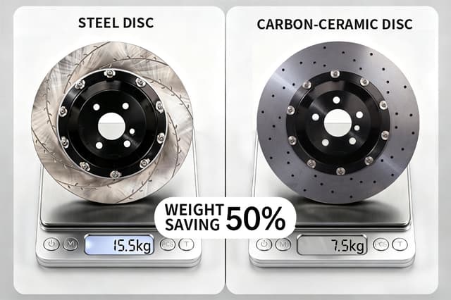
Some manufacturers describe comparable carbon ceramic discs as about 50% lighter than cast iron, depending on the application.
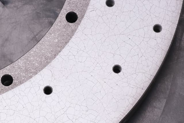
B
Friction surface
Working layer。Pad chemistry and transfer-layer stability jointly determine feel, noise and wear.
Vibration often begins with surface condition and pad deposits rather than a rotor suddenly bending.
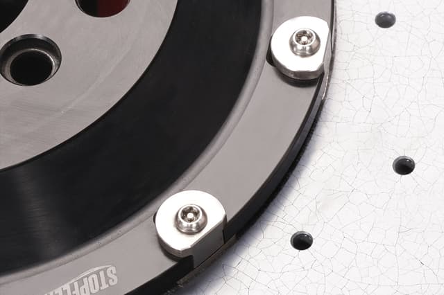
C
Hat or bell
Mounting interface。Usually aluminium, the hat defines offset, wheel clearance and thermal expansion behaviour.
Hub geometry or stack error can create runout and uneven pad contact.
D
CCB-optimised pad
Required match。Do not use a cast-iron rotor pad and expect the same result.
An unsuitable pad may destabilise the transfer layer and rapidly damage the friction surface.
Carbon ceramic compared with cast iron
Material differences become clearer after repeated stops. Thermal repeatability, dust, corrosion and rotating mass are the main variables, while one-stop distance remains largely tyre and ABS limited.
| Feature | Cast iron / steel | Carbon ceramic C/SiC |
|---|---|---|
| Fade resistance | Strong when fresh. Under sustained track heat, pads and fluid often become the limit, while iron rotors can crack or distort depending on use. | Usually offers better structural stability at high temperature. Pads, fluid and seals still require protection. |
| Brake dust | Visible dust is often higher and iron-rich dust can stain wheels. | With the correct pad, visible dust is usually lower, but never completely absent. |
| Steering and ride | Higher rotating mass asks more of the suspension over broken surfaces. | Sources often cite about 40% to 50% lower rotor mass, with the result depending on the application. |
| Stopping distance | Primarily limited by tyres and ABS. Rotor material mainly changes the thermal environment. | Still tyre and ABS limited. Pad choice can change initial bite, but rotor material alone rarely transforms a single stop. |
Cost drivers
Cast iron mainly involves casting and machining. Carbon ceramic uses a specialist material system, multi-stage high-temperature processing, harder surface finishing and stricter quality control. Scrap is costly and rework is limited.
Why the process takes longer
- Multi-stage furnace cycles involve chemical conversion, not simple heating.
- Infiltration and siliconisation require a controlled atmosphere.
- The composite cannot simply be remelted like metal, increasing quality and scrap costs.
The source gives an example of carbonisation near 900°C followed by siliconisation near 1,700°C in vacuum. Processes vary and Jietu engineering must verify these figures.
Why finishing is expensive
- SiC-based composites are extremely hard.
- Finishing often uses diamond tooling and specialist grinding.
- Runout and flatness affect NVH, so geometry control cannot be ignored.
| Cost driver | Why it raises price |
|---|---|
| Material system | Carbon fibre and silicon carbide systems cost more than ordinary iron castings, and scrap is expensive. |
| Process time | Thermal cycles and infiltration limit throughput; shortcuts can create defects or inconsistency. |
| Machining | Hard ceramic surfaces need specialist tools and slower processing. |
| Validation and QC | More inspection points, higher rejection cost and tighter final geometry. |
| Fitment engineering | Hat offset, pad sweep, wheel clearance and low-volume specifications add engineering work. |
Street and track life in reality
Street use
- Mileage has some meaning because the rotor is not continuously hot.
- The source suggests around 150,000 km as a road-use reference, depending on application and inspection limits.
- Common damage sources include edge impact, mismatched pads and careless wheel service.
Track use
- Heavy track use makes the rotor closer to a consumable, so evaluate sessions or events rather than mileage alone.
- Cooling matters: airflow and duct design can strongly change the result.
- The source gives about 2,000 km as an extreme track example. This is not a GETOP life claim.
Use-case rule
If the goal is to minimise consumable cost in frequent track use, a high-quality iron system may remain rational. Carbon ceramic value is often clearest on road and mixed use, where dust, corrosion and rotating mass matter every day.
Technical FAQ
01Should wear be measured by thickness or weight?
Do not assume one method fits every rotor. Some systems specify minimum thickness, some minimum weight and some both. Follow the markings and service instructions for that system.
02Does brake vibration mean the rotor is warped?
Not necessarily. Uneven pad transfer, incomplete bedding or holding the brakes after a hard stop are common causes. Inspect the surface, runout and bedding before declaring permanent distortion.
03Is high-temperature brake fluid required?
It is normally appropriate for hard driving and track use. Rotor cooling does not automatically protect the caliper, so choose fluid to the vehicle specification and replace it on schedule.
04Can acidic wheel cleaner be used?
Avoid strong acids and alkalis unless explicitly approved. Prefer a pH-neutral cleaner and never spray it on a hot brake system.
05Can a chipped rotor be repaired?
Structural chipping should not be treated as a cosmetic repair. Prevent impact with wheel guide pins and careful wheel handling, then follow the manufacturer's inspection limits.
Fitment and buying guide
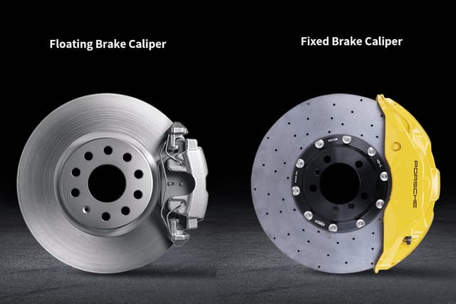
Fitment is never automatic. The rotor must match caliper type, disc size, hat geometry, pad sweep and wheel clearance.
When a rotor-only conversion may work
The vehicle already has a fixed multi-piston front caliper, and pad sweep, hat offset and wheel clearance are compatible. Fixed calipers usually clamp more evenly, supporting stable transfer and wear.
When a complete front kit is more sensible
The vehicle has a sliding or floating front caliper, or a relatively small front rotor. The source uses about 330 mm as a rule of thumb, but real fitment depends on caliper geometry, pad sweep and wheel clearance.
Fitment checklist
Provide the complete information once to reduce the risk of ordering the wrong parts.
- 01
Year / make / model:For example, 2024 BMW M4 G82.
- 02
Vehicle identification number:Confirms hub and brake variants.
- 03
Wheel size:Wheel barrel diameter and internal clearance matter.
- 04
Front brake photos:Caliper type directly changes the available options.
- 05
Current rotor size:Provide the millimetre measurement if known.
References
These links came from the user-supplied source page for internal review and technical background. An external source does not mean GETOP confirms every statement.
Need help choosing the correct brake setup?
Provide the fitment checklist and intended use, such as road, mountain or track. The right solution depends on heat load, pad match, cooling airflow and vehicle interfaces, not disc diameter alone.
Powered by Jietu New Material